
An Arduino square wave generator outputs a stable, adjustable square waveform using Arduino pins.
I have built and tuned many small test rigs using Arduino boards, and I’ll walk you through what an Arduino Square Wave Generator is, how it works, and how to build one that fits your needs. This guide blends clear definitions, step-by-step builds, code examples, and practical tips from hands-on experience so you can make a reliable generator for testing, clocks, or hobby projects.
What is an Arduino Square Wave Generator?
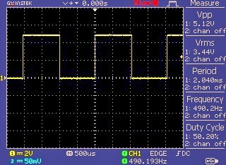
An Arduino Square Wave Generator is a circuit or sketch that makes a digital pin switch between HIGH and LOW at a steady rate. The output looks like a repeating on/off waveform. The signal is defined by two key properties: frequency and duty cycle. Frequency sets how often the wave repeats each second. Duty cycle sets how long the wave stays HIGH versus LOW in each period.
You can make a basic square wave with simple code and delay calls. For better accuracy, use hardware features like timers or PWM. People use Arduino square wave generators for prototyping, clock signals, sensor testing, and audio tones. My hands-on use shows they are fast to set up and flexible for many small tasks.

How an Arduino Generates Square Waves
There are three main ways to generate a square wave on Arduino:
- Using simple digital toggling with delay or delayMicroseconds for low precision.
- Using the tone() function to generate audio-frequency waves easily.
- Using hardware timers and direct port manipulation for precise frequency and duty cycle control.
Digital toggling flips a pin HIGH then LOW in code. This is easy but timing varies with other code tasks. The tone() function is great for tones from about 30 Hz to a few kHz. Timers give microsecond accuracy and stable frequency under load. In projects that need tight timing, I always use timers.
Building a Basic Arduino Square Wave Generator
Components you need:
- Arduino board (Uno, Nano, Mega, or similar)
- USB cable or 5V supply
- Breadboard and jumper wires
- Optional: resistor and LED for visual check, oscilloscope for verification
Simple wiring:
- Connect the Arduino GND to the circuit ground.
- Choose a digital pin, for example PIN 8.
- Optionally place a 220Ω resistor and LED between PIN 8 and GND to visualize the waveform.
Sample toggling code for about 1 kHz square wave:
const int outPin = 8;
void setup() {
  pinMode(outPin, OUTPUT);
}
void loop() {
  digitalWrite(outPin, HIGH);
  delayMicroseconds(500); // HIGH time in microseconds
  digitalWrite(outPin, LOW);
  delayMicroseconds(500); // LOW time
}
This approach is good for simple tests. For more stable frequencies, switch to timers or PWM. I often start with this code to verify wiring before moving to timer-based code.
Using Timers and PWM for Precision
Why use timers:
- Timers run independently of the main code loop.
- They keep stable timing under CPU load.
- They allow precise frequency and duty-cycle control.
On AVR Arduinos, Timer1 gives a wide range of frequencies and PWM options. Use direct register writes for best accuracy. For example, configure Timer1 in toggle-on-compare mode for a clean square wave without interrupts. Many ARM-based boards have advanced timer peripherals that do even better.
If you need analog-like control, pair a filtered PWM with a low-pass filter or use an external DAC driven by timer-driven SPI or I2C. For high-voltage or high-current signals, use a MOSFET driver or gate driver chip to protect the Arduino pin.
Advanced Methods and Techniques
Advanced options to extend capabilities:
- Direct port manipulation for faster pin toggling and higher frequency output.
- Timer compare match to create exact frequency and duty cycle.
- Phase control and multiple synchronized channels for clocking multiple devices.
- DDS (Direct Digital Synthesis) with an external DAC for very stable frequency sweeps and arbitrary waveforms.
- Buffering the output through an op amp or transistor for higher current or offset.
I once used an Arduino Square Wave Generator with a small MOSFET stage to drive a transformer for a hobby inverter test. Using a timer-based approach kept the waveform steady while my main program handled user input. When pushing frequency limits, check the microcontroller specs and avoid toggling pins faster than the MCU supports.

Practical Applications and Examples
Common uses for an Arduino Square Wave Generator:
- Function generator for bench testing and troubleshooting.
- Clock source for digital ICs and shift registers.
- PWM testing for motor drivers and LED drivers.
- Simple audio tone generation and beepers.
- Sensor excitation for devices that need square-wave input.
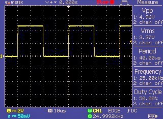
Example: I used an Arduino Square Wave Generator to test a piezoelectric sensor by driving it with a 2 kHz square wave. The sensor response was easy to measure on an oscilloscope. For audio, combine tone() with amplitude control to avoid distortion.
Benefits and Limitations
Benefits:
- Low cost and fast setup.
- Flexible frequency and duty-cycle control.
- Integrates with other Arduino functions and sensors.
Limitations:
- Output is TTL-level (0–5V or 0–3.3V) and not suitable for directly driving high-voltage loads.
- Software toggling can be imprecise under heavy CPU load.
- Maximum achievable frequency depends on MCU speed and method used.
Be honest about limits. For lab-grade signals, a dedicated function generator or DAC is better. For many hobby and prototyping tasks, an Arduino Square Wave Generator is more than enough.

Troubleshooting and Practical Tips
Common issues and fixes:
- Oscillating frequency or jitter: switch from delay-based code to timer-based generation.
- Distorted waveform under load: buffer output with a transistor or driver.
- Unexpected pin behavior: check pinMode and avoid using pins reserved for USB or serial if interfering.
- Heat or current problems: add proper drivers and never draw high current directly from the Arduino pin.
Tips from my experience:
- Always test with an LED before connecting sensitive gear.
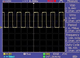
- Use an oscilloscope or logic analyzer to verify waveform shape and timing.
- Keep code simple when measuring timing; minimize interrupts and serial prints during testing.
Frequently Asked Questions of Arduino Square Wave Generator
How accurate is an Arduino Square Wave Generator?
Accuracy depends on method. Timer-based generation and direct port manipulation give microsecond-level stability, while delay-based methods vary with program load.
Can I generate audio frequencies with Arduino?
Yes. The tone() function and PWM can produce audio frequencies. For cleaner audio, use filtering or DAC solutions.
What is the maximum frequency I can generate?
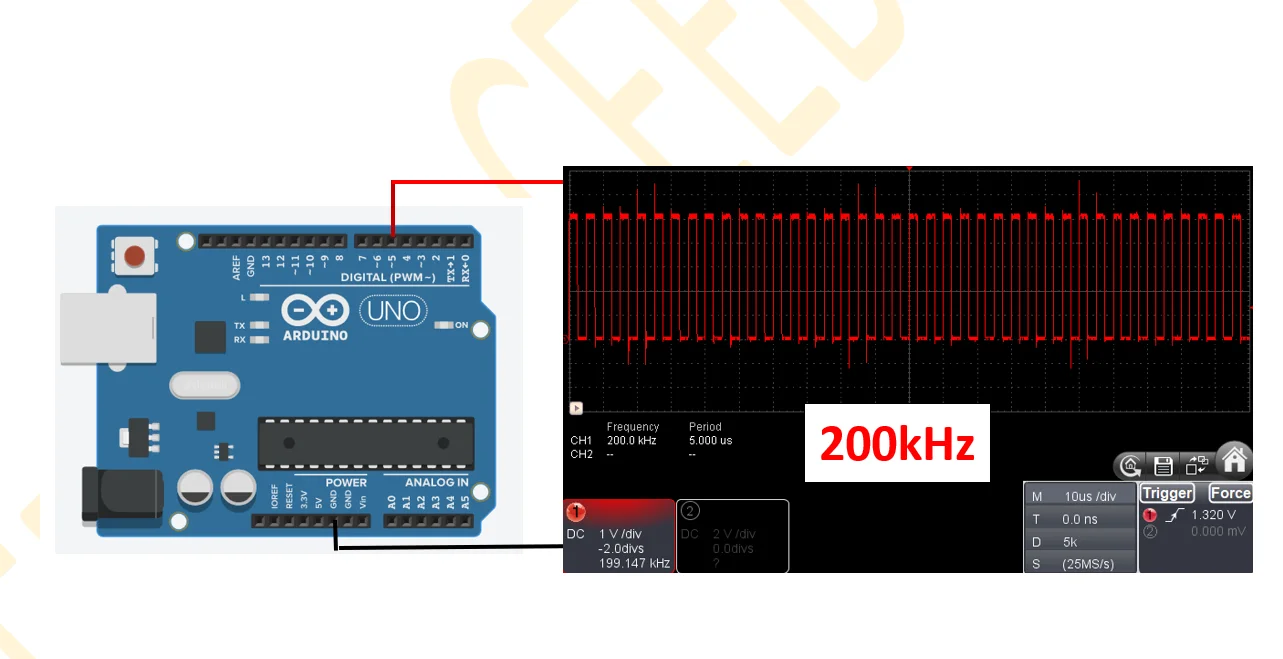
Maximum depends on MCU clock and method. Using direct port toggling on a typical 16 MHz AVR, you can reach several MHz, but quality and duty control fall off near limits.
Do I need external components to protect the Arduino pin?
Yes, for driving loads above a few milliamps. Use transistors, MOSFETs, or driver ICs to prevent damage and isolate the pin.
How do I make a variable duty cycle square wave?
Use timers with PWM modes or adjust compare-match values. This allows precise control of HIGH and LOW durations per cycle.
Can I synchronize multiple square waves?
Yes. Use timers that support multiple compare channels or use hardware timers with synchronized triggers. This keeps phase and frequency aligned.
Conclusion
An Arduino Square Wave Generator gives you a low-cost, flexible tool for generating precise digital signals for testing and prototypes. Start simple with digital toggling, then move to timers or external DACs for higher precision. Try a small build, verify with an oscilloscope, and scale up with buffering or drivers when needed. If you enjoyed this guide, try building a small generator today, share your results, or subscribe for more Arduino projects and tips.