How do you connect solar panels in series? In a series string, the positive lead of one solar module connects to the negative lead of the next module. The remaining free negative and positive leads become the two ends of the string, which connect to compatible solar-input equipment through the protection and wiring required by the system design. With closely matched panels, their voltages add together while the string current stays approximately equal to the current of one panel. Before making any physical connection, verify the cold-weather open-circuit voltage and every inverter or charge-controller input limit.
This guide explains the connection layout, the calculations that determine whether it is compatible, and the safety checks that must happen first. It is a planning and educational guide, not authorization to wire a live rooftop array. Solar panels can produce hazardous DC voltage whenever illuminated; permanent or high-voltage systems should be designed and installed by qualified professionals under the applicable electrical code.
What Does Connecting Solar Panels in Series Mean?
A series connection makes one continuous electrical path through multiple panels. Think of it as a string: one panel’s positive output is joined to the next panel’s negative input, continuing through the intended number of modules. Unlike a parallel connection, the positive outputs are not all grouped together and the negative outputs are not all grouped together. The important electrical result is that the individual panel voltages are added.
Solar manufacturer Renogy explains the series principle and contrasts it with parallel wiring. The choice is determined by the receiving equipment and the array design—not by a blanket claim that series is always better. For a separate overview of both layouts, see our solar panel series vs. parallel comparison.
Simple two-panel connection diagram
Panel 1 (+) ───── Panel 2 (−)
Panel 1 (−)       Panel 2 (+)
     │                │
     └── String (−)   └── String (+)
          to compatible solar input,
          via approved wiring and protection
The diagram illustrates polarity and topology only; it deliberately omits the system-specific disconnects, fuses, grounding, cable ratings, and other required protection. A real installation must follow the exact panel and inverter manuals and be checked for the maximum voltage that can occur in cold conditions. Never rely on connector shape alone to determine polarity.
Step 1: Identify the Exact Solar Panels and Receiving Equipment
Start with the model number of every panel and the model of the charge controller, hybrid inverter, string inverter, or portable power station that will receive the power. Obtain the manufacturer’s actual manuals and electrical datasheets. A general video showing two 100-watt panels does not establish that the same connection is safe for two larger modules or a different controller.
Record each panel’s maximum-power voltage (Vmp), maximum-power current (Imp), open-circuit voltage (Voc), short-circuit current (Isc), and the temperature coefficient of Voc. Also note the maximum permitted series fuse rating, module maximum system voltage, and any manufacturer instructions about mixing modules. For the receiver, record maximum PV input voltage, MPPT operating voltage range, input current, short-circuit current limit, total supported PV power, connector type, and any specified startup conditions.
The difference between Voc and Vmp is essential. Vmp describes voltage near the maximum-power operating point. Voc is the voltage when the module is not delivering current. It is Voc, adjusted for cold conditions, that is particularly important for checking the receiver’s absolute maximum voltage. The Victron installation manual explicitly warns that open-circuit voltage rises at low temperatures and must be considered when deciding how many panels may be connected in series.
Step 2: Calculate the Series Voltage Before Connecting Anything
For matched modules under the same reference conditions, the series-string operating voltage is approximately the sum of their Vmp values. Likewise, the series open-circuit voltage is the sum of the individual Voc values. The string operating current is approximately the current of one matched panel; it is not the sum of panel currents. These calculations explain the arrangement, but they do not replace a proper temperature and equipment-compatibility check.
| Illustrative panel specification | One panel | Two in series | Three in series |
|---|---|---|---|
| Maximum-power voltage (Vmp) | 30 V | 60 V | 90 V |
| Open-circuit voltage (Voc) | 36 V | 72 V | 108 V |
| Maximum-power current (Imp) | 10 A | 10 A | 10 A |
| Idealized power at Vmp × Imp | 300 W | 600 W | 900 W |
These are invented arithmetic examples, not specifications of a real panel. A three-panel string with 108 V of reference-condition Voc could already exceed a controller rated for 100 V maximum PV input, even before cold-weather adjustment. It would be unsafe to select that configuration for such a controller. Never use the lower 90 V Vmp figure to argue that the 100 V maximum is satisfied.
Step 3: Account for the Coldest Expected Conditions
Panel open-circuit voltage generally increases as the cells become colder. A series string that appears to fit an input limit on a warm afternoon may exceed it on a cold, sunny morning. The correct calculation uses the panel’s published Voc temperature coefficient, the reference temperature in its datasheet, and the design minimum temperature required for the installation location and applicable standard.
As a simplified hypothetical example, suppose a panel has Voc of 36 V at 25°C and a Voc temperature coefficient of −0.30% per °C. If the cell temperature is −10°C, the difference is 35°C below the reference. A first-order estimate of the Voc increase is 35 × 0.30% = 10.5%, giving about 39.78 V per panel. Three such panels could reach roughly 119.34 V open circuit. That calculation is an illustration, not a certified design value; the manufacturer’s exact coefficient convention and required design method must govern.
A professional designer will also evaluate equipment maximum voltage, component ratings, allowable tolerances, and any code-mandated adjustment factors. Victron’s PV array instructions specifically require both Voc and its temperature coefficient when calculating series-string length. If the calculation is near a limit, do not proceed on a guess or a rounded figure.
Step 4: Check the MPPT Range and Current Limits
Maximum voltage is not the only compatibility requirement. A solar charger or inverter also has an operating window where it can track power effectively. A string may be safely below the absolute maximum yet have too little voltage to start or remain inside the MPPT range during hot weather. Panel operating voltage typically decreases as cells get hotter, so both cold and hot operating conditions matter.
For battery charging, some MPPT controllers require PV voltage above battery voltage to begin charging. The exact startup margin is model-specific. The Victron SmartSolar manual, for example, describes its own minimum PV-to-battery voltage conditions; those are not universal rules for every inverter or portable station. Check the precise model’s manual, not an internet formula borrowed from another device.
Series wiring does not increase current by adding each panel’s amperage. Still, the string’s Imp and Isc must satisfy the receiving equipment’s limits, and the conductor and protective-device design must be suitable. An input advertised as accepting 800 W of solar is not necessarily safe at any voltage/current combination totaling 800 W.
Step 5: Match Panels, Connectors, and Cable Specifications
Modules within one string should generally have compatible electrical characteristics. A significantly lower-current panel can constrain current through the whole series path, and differences in cell architecture, bypass diode behavior, shading, or degradation can further complicate performance. Matching only the wattage printed on two labels is not enough. Manufacturer documentation may specify which module combinations are permitted.
Check the connector family, connector manufacturer compatibility, cable type, insulation and voltage ratings, environmental rating, and the system’s required protection. Some solar connectors look alike but are not approved to mate with different brands or generations. The Renogy module installation manual stresses electrical compatibility, maximum system voltage, and avoiding shading.
A series connection usually joins opposite-polarity module leads in sequence rather than using the Y-shaped branch connectors typically associated with parallel connections. However, that description is not a substitute for the connector manufacturer’s mating, assembly, and disconnection instructions. Never cut or improvise energized solar cables or assume an adapter makes an incompatible input safe.
Step 6: Plan the Series String and Its Protection
Once the engineering checks are complete, the installer prepares the approved wiring layout showing each panel, string endpoints, cable route, input equipment, disconnects, protective devices, grounding and bonding, and any required rapid-shutdown system. For a small portable kit, the approved arrangement may be simpler; for a rooftop grid-connected system, code requirements and hazards are substantially more involved.
The conceptual connection order is straightforward: one panel’s positive lead is paired with the next panel’s negative lead until the specified string is formed, leaving a positive and negative endpoint. But the physical connection and commissioning procedure must follow the manufacturer’s instructions and safe electrical work practices. Panels can be energized in sunlight, and DC arcs can be dangerous. Qualified installers should control exposure, isolate equipment appropriately, use approved tools, and verify the system before energizing it.
Do not disconnect solar connectors under load unless the equipment explicitly permits that operation and the specified procedure is followed. Do not touch exposed conductor ends. The Victron EasySolar manual warns installers to protect modules from incident light during installation, use insulated tools, and avoid uninsulated cable ends. Those precautions underscore why permanent high-voltage wiring is not a casual DIY task.
Step 7: Verify Polarity and Commission the System Safely
A qualified installer verifies that the finished string has the expected polarity and voltage under the conditions at the time of testing, and that the result is consistent with the engineered design. The installer also checks insulation, protective devices, grounding and bonding where required, connector integrity, and the equipment’s commissioning procedure. An ordinary handheld voltage reading is not proof that cold-weather maximum voltage or all code requirements have been satisfied.
Follow the equipment manufacturer’s required sequence for battery and PV connections; different controllers and inverters can have different instructions. Do not guess that the solar side should always be connected first or that an inverter can safely accept reverse polarity. If a controller displays a fault or a reading outside the expected range, stop and seek qualified assistance rather than repeatedly reconnecting the array.
How Many Solar Panels Can You Connect in Series?
The maximum number depends on the panel Voc at the design minimum temperature, the receiving device’s maximum input voltage, and the module and wiring ratings. The minimum useful number may depend on the receiver’s MPPT and startup voltage requirements at high operating temperatures. There is no universal answer such as ‘always two,’ ‘always four,’ or ‘always ten.’
A preliminary upper-bound calculation divides the receiving equipment’s maximum allowed PV voltage by the temperature-adjusted Voc per panel, then rounds down to a whole panel. That is only one constraint, not a complete design. Other checks may force a smaller string or different equipment. A qualified designer should document both maximum cold Voc and minimum hot operating voltage for the proposed string.
Series vs. Parallel: Which Connection Should You Use?
| Design question | Series connection | Parallel connection |
|---|---|---|
| What adds? | Panel voltages | Branch currents |
| What remains roughly unchanged for matched panels? | String current | Array voltage |
| Primary input-limit concern | Cold-weather open-circuit voltage | Total current and branch protection |
| Typical connector topology | Positive-to-negative chain | Positive-to-positive and negative-to-negative branches |
| Shade and mismatch | One module can constrain string behavior | Branch behavior differs; shading still matters |
Series wiring can reduce conductor current for a given power level compared with a lower-voltage arrangement, which may help reduce certain cable losses in an appropriately engineered design. But that does not make it the right choice for every battery charger, portable station, or rooftop array. The final decision should account for the receiver’s electrical window, cable distance, module matching, shade, protection, and local requirements.
Common Mistakes When Connecting Panels in Series
- Checking only panel wattage: the receiver must also accept the resulting voltage and current.
- Using Vmp instead of Voc for the maximum-voltage check: cold open-circuit voltage can be considerably higher.
- Ignoring temperature: a design that appears acceptable at 25°C can violate a voltage limit in colder weather.
- Mixing dissimilar panels: current mismatch and manufacturer restrictions can reduce performance or invalidate the proposed design.
- Assuming matching connectors are safe: connector compatibility depends on actual approved models and ratings.
- Making or breaking live connections: illuminated PV modules can sustain dangerous DC arcs.
- Skipping protective equipment: the system may require disconnects, overcurrent protection, grounding, rapid shutdown, and inspection.
- Connecting directly to a battery without suitable control: use the manufacturer-approved charge-control and protection arrangement.
Can You Connect Solar Panels in Series to a Portable Power Station?
Sometimes. Many portable power stations accept solar charging, but their permitted voltage range and current limits vary by model. Connecting two portable panels in series may fit one model and damage another. Verify the maximum total cold Voc, supported input current, solar charging wattage, connector arrangement, and any manufacturer limits on panel combinations.
If a portable station supports two separate solar inputs, do not assume those inputs are electrically interchangeable or can be combined without following the manual. For additional context, see our guide to solar generators. The correct wiring arrangement is a property of the exact station and panels, not the brand name alone.
Frequently Asked Questions
How do you wire two solar panels in series?
Conceptually, the positive terminal of one panel is connected to the negative terminal of the other, leaving the two outer terminals as the string endpoints. Before anyone physically connects them, the combined cold-condition Voc, operating voltage, current, connector compatibility, and required protection must be checked against the receiving equipment’s manual.
Does connecting solar panels in series increase watts?
Adding a second matched panel increases the total available array power because there is another panel collecting sunlight. The series arrangement itself primarily changes the voltage-current combination; it does not magically create extra power compared with the same panels connected in a compatible parallel configuration under identical ideal conditions.
Do solar panels in series need a charge controller?
If the series string is intended to charge a battery, a suitable approved charging system is required. The exact hardware depends on the system. Do not connect an uncontrolled PV string directly to a battery simply because the nominal voltage appears similar.
Can I connect different wattage solar panels in series?
It may be technically possible in some supported designs, but different electrical characteristics can cause mismatch losses and compatibility problems. Compare Imp, Vmp, Voc, Isc, and manufacturer restrictions. Use matched modules when practical and seek a reviewed design for mixed panels.
Can three 12V solar panels be connected in series?
A ’12V panel’ label is often a nominal application description, not its actual Voc. Three panels might exceed a small controller’s input limit. Use the exact panel datasheets, calculate cold-condition Voc for all three, and verify the charge controller’s specifications before deciding.
What happens if one panel is shaded?
Partial shade can reduce the current and power of a series string, depending on the module design and bypass-diode operation. Real effects are more complex than assuming every panel always produces the same power. Assess site shading and compare alternatives before choosing the array layout.
Do you need special connectors for series wiring?
You need connectors and cables specifically approved for the panel models, voltage, current, and installation environment. Series strings often use compatible module leads, while parallel arrays commonly use branch connectors. Never assume two visually similar connectors are safe to mate.
Final Checklist Before Series Wiring
Collect panel and receiver datasheets, verify the proposed string’s cold Voc and hot operating voltage, confirm all input-current and power limits, use compatible connectors and appropriately rated protection, and follow the equipment’s commissioning instructions. If any specification is missing, stop and obtain it rather than improvising. For a rooftop or permanently installed system, have the work completed and inspected by qualified professionals.
Bottom line: solar panels in series are connected positive-to-negative so that their voltages add. That basic concept is simple; confirming that the resulting DC string is safe for the controller or inverter is the critical part. Correct sizing and installation matter more than copying a generic wiring picture.
References and Image Credit
- Renogy: Series, Parallel and Series-Parallel Connections
- Renogy: How to Set Up Panels in Series
- Victron: SmartSolar MPPT Installation Manual
- Victron: Higher-Voltage MPPT Installation Manual
- Renogy: PV Module Installation Manual
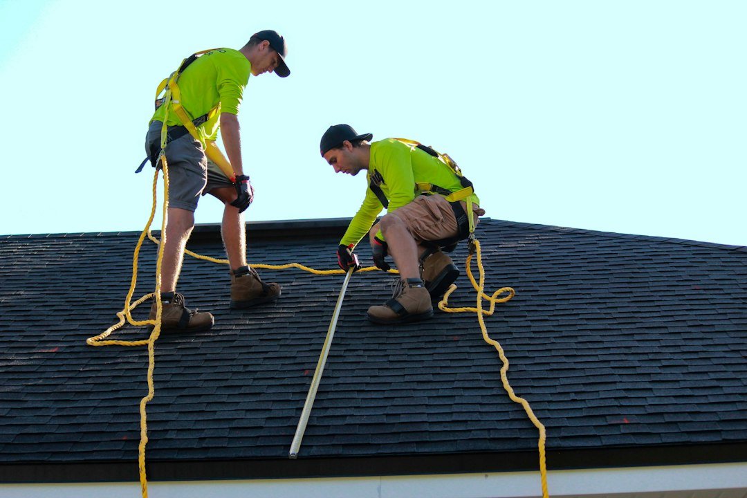
Safety and editorial note: Numerical examples are illustrative and do not constitute an approved wiring design. Photographic illustration: Raze Solar / Unsplash; it shows solar installation work, not the specific connection described.