
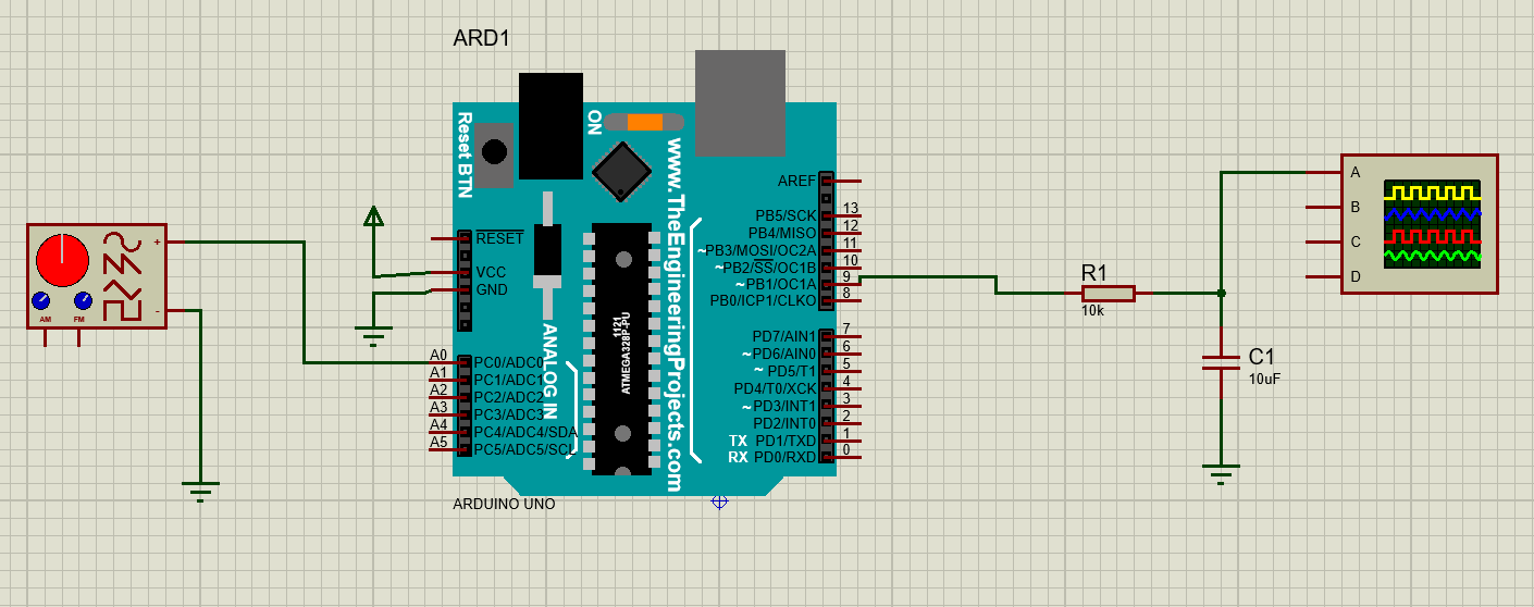
An Arduino sine wave generator creates smooth AC-like signals using code, PWM, or an external DAC.
I build and test Arduino Sine Wave Generator projects often. I will walk you through how these generators work, which methods to use, and real-world tips I learned from hands-on builds. This guide covers theory, circuits, code snippets, parts lists, troubleshooting, and project ideas so you can build a reliable Arduino Sine Wave Generator for audio tests, sensors, or hobby electronics.
Overview: What is an Arduino Sine Wave Generator and why use one
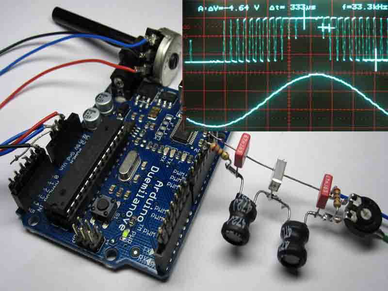
An Arduino Sine Wave Generator is a circuit and firmware combo that produces a repeating sine waveform. The waveform can be used for audio, signal testing, sensor stimulation, or educational demos. The Arduino microcontroller controls timing and amplitude to shape the output.
Why build one with Arduino
- Low cost and wide availability.
- Easy programming and many example libraries.
- Flexible frequency range from sub-hertz to tens of kilohertz depending on method.
- Great learning project for microcontroller timing, DACs, and filters.
Common terms to know
- DAC: Digital-to-Analog Converter that outputs voltage levels.
- PWM: Pulse Width Modulation used as a crude DAC.
- DDS: Direct Digital Synthesis, a method for precise waveform generation.
- LPF: Low-Pass Filter to smooth PWM into analog waveforms.
An Arduino Sine Wave Generator can be simple or advanced. I will show both simple PWM builds and higher-quality DAC-based solutions so you can choose based on cost, quality, and complexity.

How an Arduino Sine Wave Generator works
Core idea
- The microcontroller outputs digital values that represent sine amplitudes.
- A converter and filter turn those digital values into an analog voltage.
- Timing controls the sine frequency.
Step-by-step flow
- Create a lookup table of sine values in code.
- Output values at fixed time intervals.
- Use hardware (DAC or PWM+LPF) to convert values to analog.
- Optionally amplify or buffer with an op amp.
Timing and resolution matter
- Sample rate determines maximum clean frequency (Nyquist rule).
- Bit depth (DAC resolution) controls waveform granularity.
- Jitter in timing adds noise and distortion.
Practical limits
- Arduino Uno native DAC is not available; PWM or external DACs are common.
- Using PWM needs proper filtering for low distortion.
- External DACs give cleaner output but cost more.

Source: simple-circuit.com
Methods to make an Arduino Sine Wave Generator
Below are common approaches ranked by quality and complexity.
Method: PWM plus RC low-pass filter
- Uses built-in PWM pins.
- Software outputs varying duty cycles from a sine table.
- A simple RC filter smooths the PWM into an analog voltage.
Pros - Very low cost and simple.
Cons - Moderate distortion, limited top frequency, depends on PWM base frequency.
Method: R-2R ladder DAC
- Uses resistors in a binary ladder to create multiple voltage levels.
- Controlled by digital pins to output a pseudo-analog level.
Pros - Medium cost, no external ICs.
Cons - Requires many pins and precise resistors for good linearity.
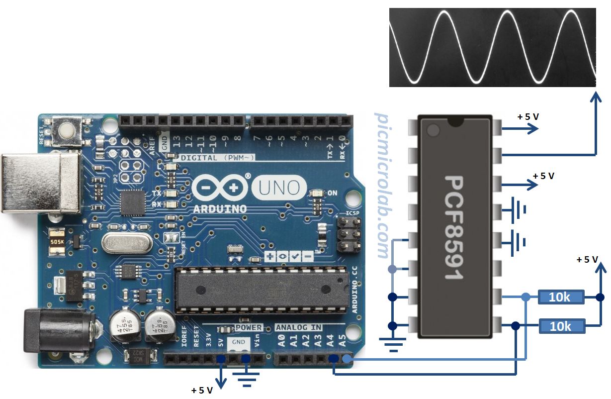
Method: External DAC (SPI/I2C) like MCP4725 or MCP4921
- Uses a true DAC IC controlled by I2C or SPI.
- Outputs clean voltages with known resolution.
Pros - High-quality output for audio or measurements.
Cons - Slight cost and wiring complexity.
Method: DDS or timer-driven DAC
- Uses precise timers for sample timing.
- Often paired with an external DAC for best results.
Pros - Very accurate frequency control and low jitter.
Cons - Requires more advanced coding and understanding of timers.
Method: Audio shield or sound card
- Uses dedicated audio hardware for best fidelity.
Pros - Plug-and-play, high quality.
Cons - More expensive and may be overkill for simple tests.
Choosing a method depends on goals. For audio demos, choose an external DAC. For simple tests and learning, PWM works well. I used PWM to teach students and a DAC for lab-grade signals.
Components and circuit examples for Arduino Sine Wave Generator
Minimal PWM build
- Arduino Uno
- 1 kΩ resistor and 10 nF to 10 μF for RC filter (values tune filtering)
- Optional op amp for buffering
Wiring - PWM pin to resistor then to ground with capacitor at output node.
- Output node buffered by op amp if driving loads.
R-2R ladder build
- 8 resistors of value R and 8 resistors of 2R for an 8-bit ladder.
- Connect digital pins to the ladder inputs.
Notes - Use 1% tolerance resistors for better linearity.
- Buffer output with op amp.
External DAC build
- Arduino
- MCP4725 (I2C) or MCP4921 (SPI) DAC module
- I2C or SPI connections to Arduino
- Output smoothing is minimal; add buffer if needed.
Example circuit tips
- Use AC coupling for audio output to remove DC offset.
- Add a small op amp to shift and amplify voltage range.
- Use proper ground layout to reduce noise.
Parts checklist
- Arduino board
- DAC module or resistors for ladder
- Passive components for filter
- Breadboard or PCB
- Oscilloscope or multimeter for testing
I once built an Arduino Sine Wave Generator using MCP4725 to drive a small speaker for a doorbell emulator. The DAC removed the buzzy tone I had with PWM.

Software and code patterns for Arduino Sine Wave Generator
Basic code outline
- Build a sine lookup table using floating or integer math.
- Use millis or hardware timers for timing. Timers give more stable frequency.
- Write values to DAC or PWM at each sample tick.
Sine table example pattern
- 256-sample table for smooth shapes
- Use integer math for speed on AVR chips
- Interpolation can reduce quantization at lower table sizes
Timer use
- Use Timer1 on Uno for precise interrupt-based sample output.
- Avoid delay() inside main loop to maintain steady timing.
Libraries and tools
- Use available DAC libraries for MCP4725 or other chips.
- Use DMA-capable boards (like Teensy) for high sample rates.
Sample rate guideline
- For audio up to 20 kHz, use sample rates >= 44.1 kHz.
- For test signals lower than 1 kHz, 4–8 kHz sample rate often suffices.
Code tip from my experience
- Start with small sample tables and test on scope.
- Move to hardware timers only after logic works.

Source: picmicrolab.com
Applications and projects for Arduino Sine Wave Generator
Hobby and learning
- Teach signal theory.
- Create audio tones and effects.
- Control lab experiments.
Practical uses
- Sensor excitation for capacitance or impedance testing.
- Simple function generator for electronics bench work.
- Low-frequency stimulation for analog circuits.
Creative projects
- Generate music tones with frequency sweeps.
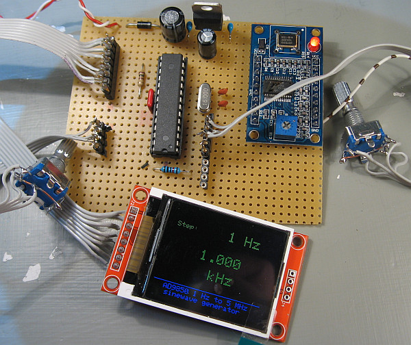
- Build a DIY signal generator with frequency knob and display.
- Create modulation experiments (AM/FM) to learn communications basics.
My favorite small project
- A handheld function generator with rotary encoder and small OLED. The Arduino Sine Wave Generator produced clean test tones and fit in a small box.

Source: youtube.com

Design tips, measurement, and troubleshooting
Measure and verify
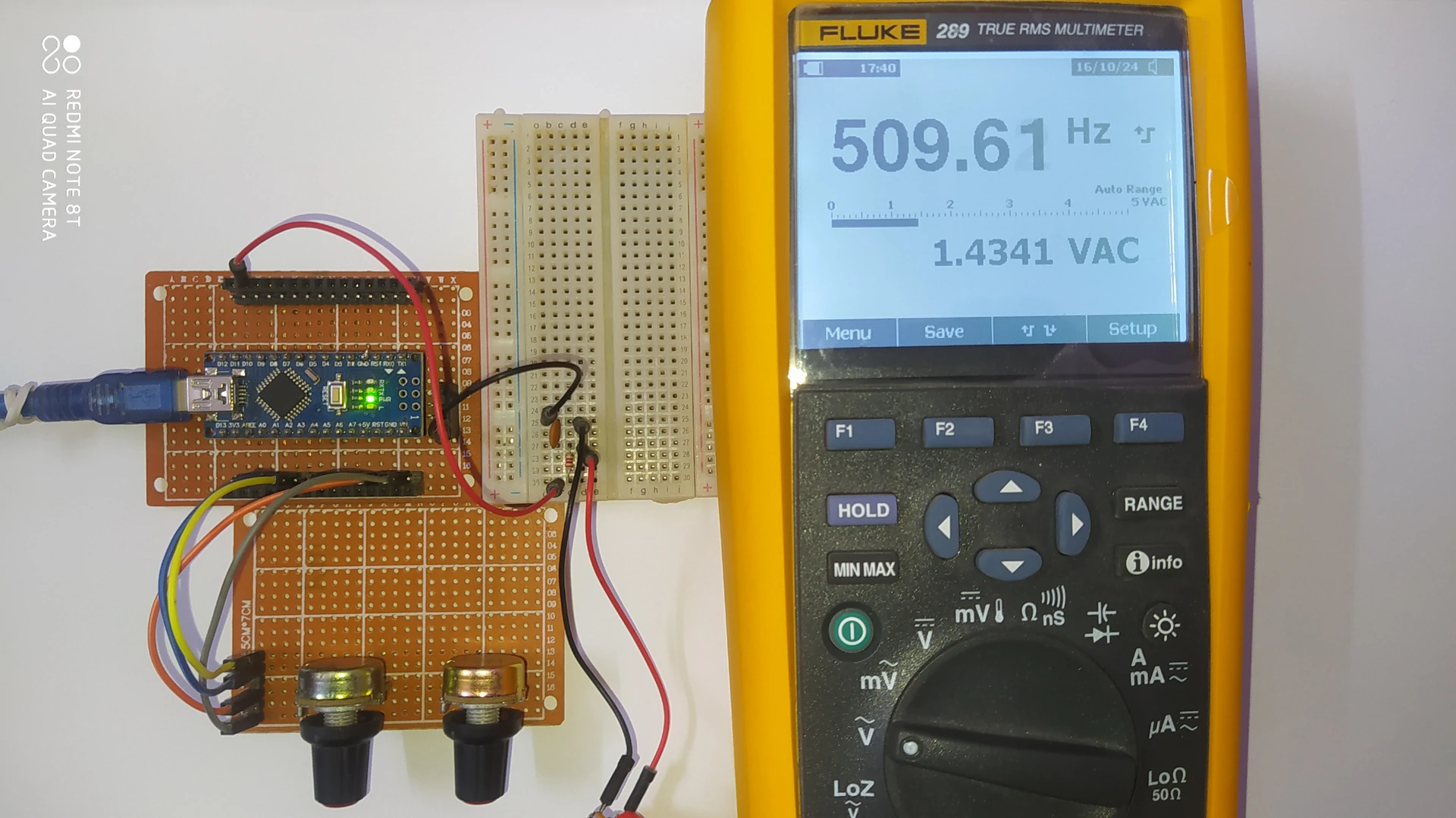
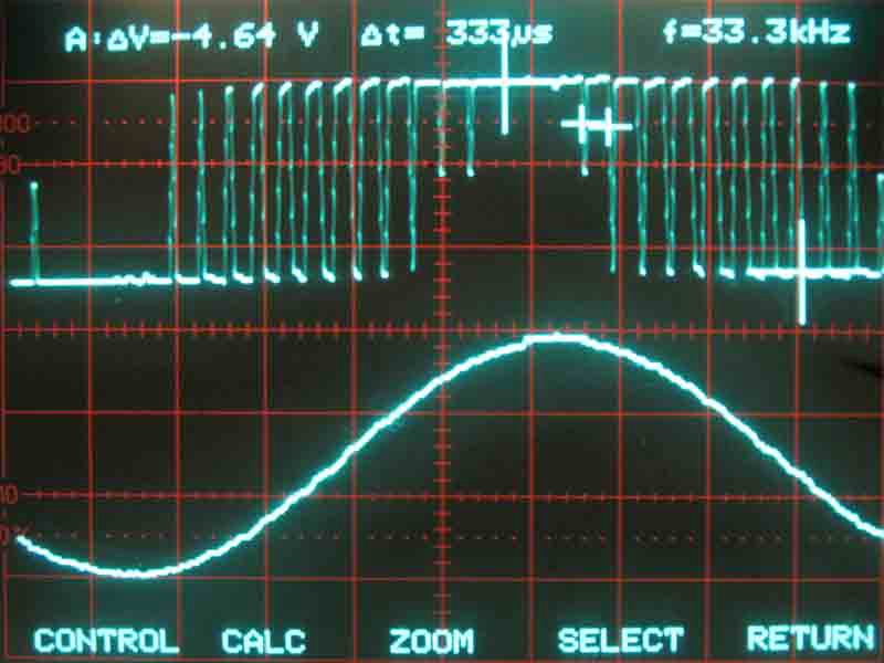
- Use an oscilloscope to check waveform shape and jitter.
- Measure THD (total harmonic distortion) if fidelity matters.
Common issues and fixes
- Distorted output from insufficient filtering: increase filter order or use DAC.
- Noisy ground: tie grounds together and shorten ground loops.
- Frequency drift: use timers rather than delay().
Performance trade-offs
- PWM is cheap but noisy.
- External DACs are cleaner but cost more.
- Higher sample rates reduce aliasing but increase CPU load.
Practical tips
- Use interpolation to smooth small lookup tables.
- Keep sample buffer updates outside the main loop.
- Use decoupling caps on power pins for DACs and op amps.
From hands-on experience, the biggest mistake is underestimating filtering needs. Early builds that sounded good on a multimeter often sounded poor on a speaker. Proper filtering and buffering fixed most issues.
Limitations and alternatives to Arduino Sine Wave Generator
Known limitations
- Limited sample rate and memory on small Arduinos.
- PWM will never match true DAC fidelity.
- Output amplitude range limited to board supply rails.
Alternatives
- Use a Teensy board for high-quality audio with built-in DACs.
- Use dedicated waveform generator ICs for professional test equipment.
- Use PC-based sound cards for high-resolution audio generation.
When to choose Arduino
- Good for education, prototyping, and low-cost projects.
- Not ideal for lab-grade signal generation without an external DAC.
Be transparent
- Expect trade-offs between cost, quality, and complexity.
- State your project goals before choosing a method.
Common questions people ask (PAA-style)
What sample rate do I need for an Arduino Sine Wave Generator?
- Sample rate should be at least twice the highest frequency you need. For clean audio, target 44.1 kHz or higher.
Can I make stereo output with Arduino?
- Most Arduinos lack two hardware DACs; you can use two external DACs or a board with stereo DACs like some shields or Teensy models.
Is PWM good enough for audio tests?
- PWM is fine for low-fidelity tones and education. For low distortion audio tests, use an external DAC.
How do I get higher amplitude than Arduino output?
- Use an op amp or amplifier after the DAC or filter. AC coupling can remove DC offsets safely.
Do I need an oscilloscope to build one?
- An oscilloscope helps a lot but a multimeter and a headphone test can suffice for basic checks.
Frequently Asked Questions of Arduino Sine Wave Generator
What is the simplest way to make a sine wave with Arduino?
Use PWM with a sine lookup table and an RC low-pass filter. This method is cheap and easy to prototype.
Which Arduino board is best for sine wave generation?
A board with more memory and timers, or native DAC like Teensy, is best. Uno is fine for simple tasks but has limits.
How accurate is an Arduino-based sine wave generator?
Accuracy depends on method: PWM is least accurate, an external DAC gives good accuracy, and Teensy-level DACs give high accuracy.
Can I change frequency on the fly?
Yes. Update the timer or sample interval in code, and the Arduino Sine Wave Generator will change frequency in real time.
How do I reduce noise and distortion?
Use a higher sample rate, better filtering, external DACs, and proper grounding. Buffer outputs with op amps to drive loads.
Can I generate multiple waveforms at once?
Yes with multiple DACs or using fast microcontrollers and DMA. On basic Arduinos, resources limit concurrent channels.
Conclusion
An Arduino Sine Wave Generator is a versatile project that teaches timing, DAC concepts, and signal design. You can start cheap with PWM and grow to external DACs for better quality. Think about your goals, pick the method that fits, and debug with simple measurements. Try a small PWM prototype first, then upgrade to a DAC when you need better fidelity. Share your builds, ask questions, or subscribe for more tutorials and code examples.